Circuits and Codes
ABIZO Health Care Kit
Posture Keeper and Smart Hydration Water Bottle
ABIZO circuit
My idea bisiclly to build a robot that can intract with the kids, and be as a puster keeper, beased on the robotic dancing teapot.
made by Paul-Louis Ageneau, and based on Otto DIY robot DIY. I add on the code more features to achive my idea.
In this project I used two circuits one for the robot and the other one for the Smart hydration water bottle, below I will expline more about each one of them.
ABIZO Robot board
My biggest challange wes the volt! when I did the testing by using arduino it dosen't worked. After many trails with diffrent voltage, I burned 2x servo motors, so I search for 5V adapter and I found one at my home, I cut the USB data cable then I used the red and the black wires.
Finally it works!
First prototype part 1
Electronices components:
Code
First prototype part 2
Electronices components:
Code
Fisrt protoype worked amazing!
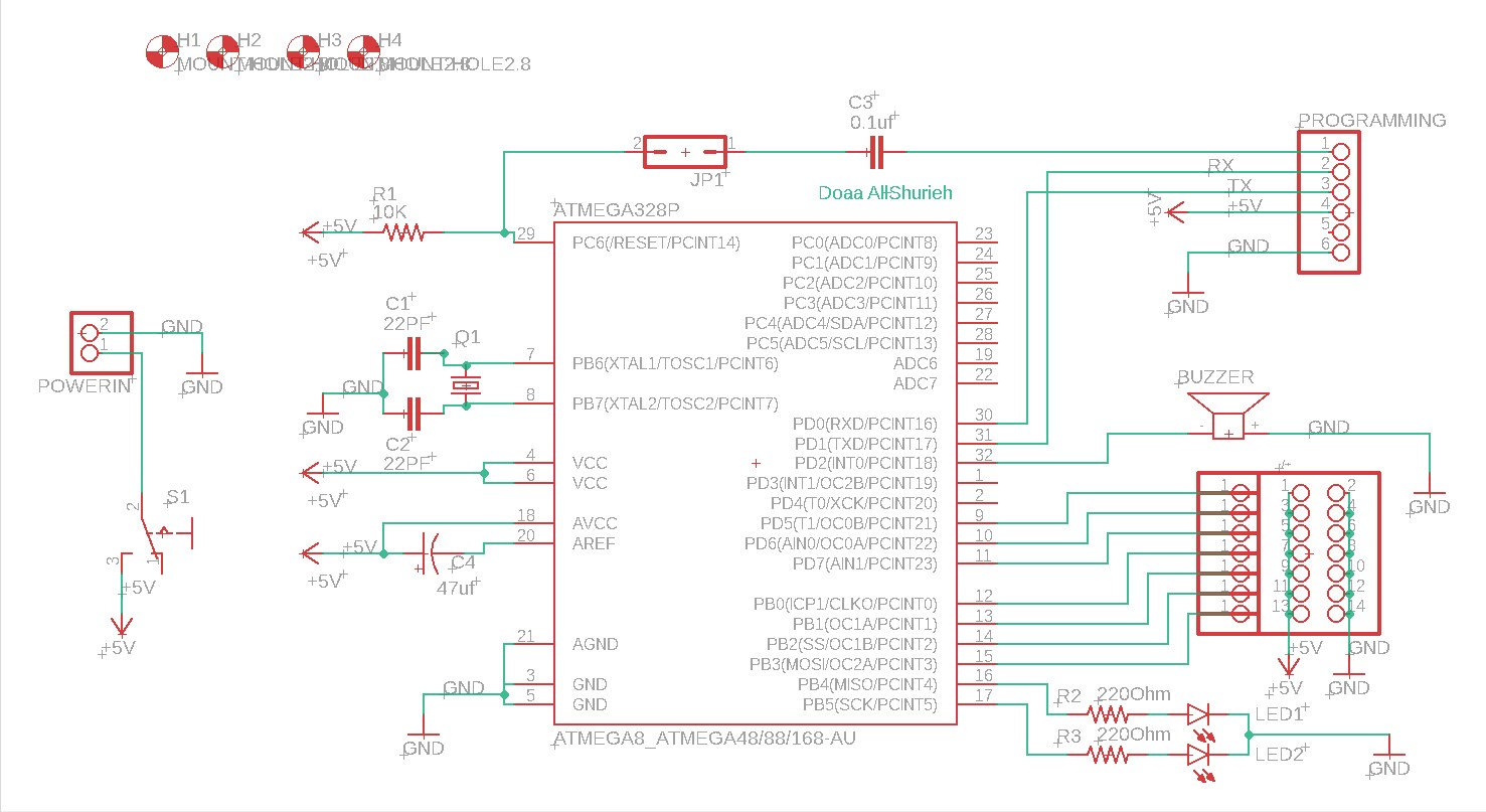
ABIZO Robot PCB Circuit
In this project I designed the board by using eagle beased on two boards first Eng. Yousef Alsenwar board in his final project. and my board on Electronics Design week. After I read more about the I/O pin for the microcontrollers on Embedded Programming weekI decided to use ATmega328 for the robot and Attiny 44 for the smart hydration water bottle. In this board I asked one of the experts to help me to arrange the board with more components. So I devloped my boardes to work more efficiently by adding the below compounentes for the robot pcb:
- 1x ATmega328
- 2x Capacitor 22PF
- 1x Capacitor 0.1uf
- 1x Resistor 10K
- 2x Resistor 220ohm
- 1x Capacitor 47uf
- 29x Pin headers
- 1x Crystal
- 5x Micro Servo motor 9G
- 1x Switch
- 1x 5V adapter
- 1x Ultrasonic
- 2x LED
- 2x Buzzer
- 1x Wire to board terminal
In this board I used crystalto produces stable output for prolonged time, I couldn't find lithium battery so I used 5v adabter to maker sure all the micro servo will work. Schematic Drawing
Board Drawing

The Hydration bottelPCB Circuit
This is the second product of my final project. In this prototype, I design a refillable smart hydration water bottleit should be free BPA, a long-lasting battery. The water bottle will interact with the kid by lighting up the LED strip while drinking water to show the water level and the amounts.
The eariller the bettter
This is the main feature, I designed the kit to help the early age studesnt to keep the neutral spine and creat healthy good habbits during studing time, because while the lockdown of the schools during covid 19, I observed many bad habbit the kids forget to drink enough water during the virtual classes and the setting on many differnt places at home with bad poster. When the teacher asked them to go to break withen 15min most of the kids setting and playing on the computer games until the the next class begain. By this project am looking to change these habbits and help the perants to builed better hydration habbits from an early ages, keep the kids active.
First prototype
Electronices components:
Code
Hydration bottel main circuit
In this project I designed the board by using eagle by adding the below compounentes:
- 1x Attiny 44
- 4x Resistor 10K
- 13x Pin holder
- 1x RGB LED
- 1x terminal pin holder
Schematic Drawing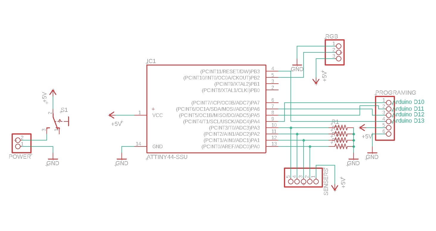
Board Drawing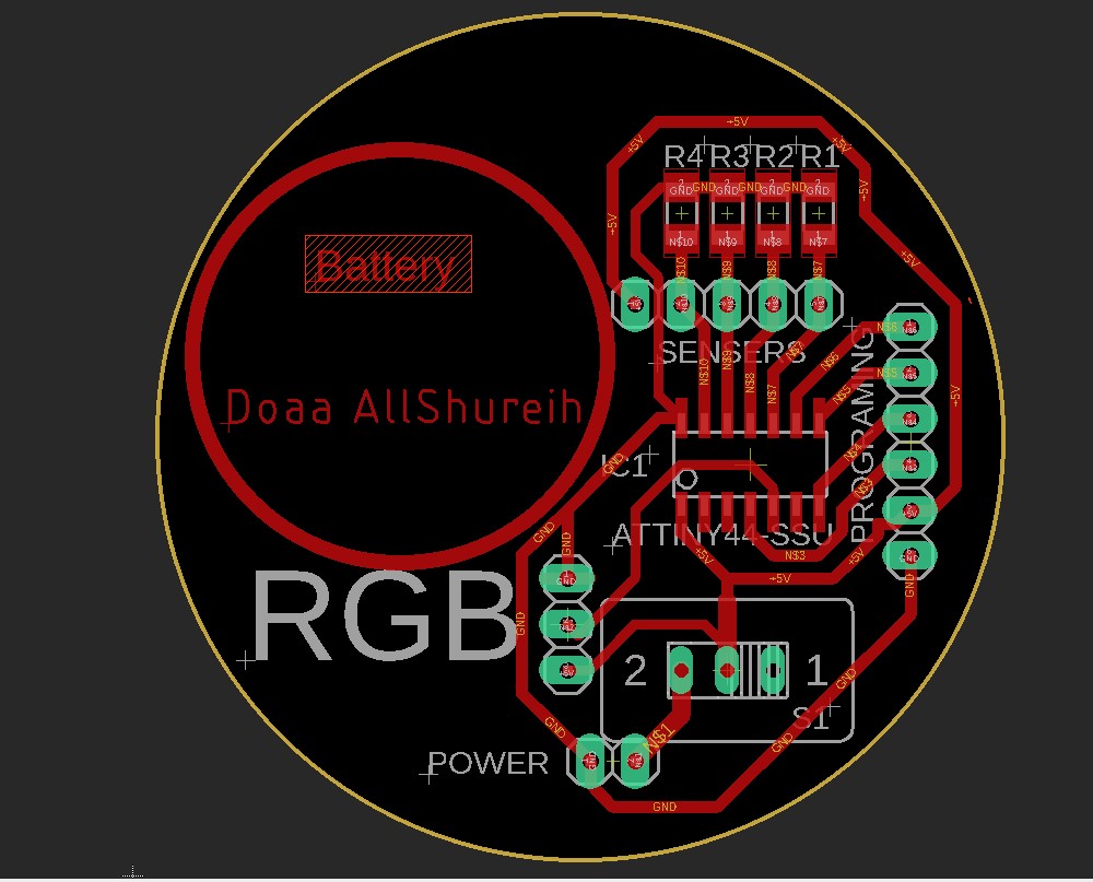
ABIZO Kit PCBs Fabrication
After I exported the circit to .png, I used inkscape to traced it then saved it as svg. By using Easel I milled my board, with the follwing setting:
Milling - Bit : 1/64 in = 0.015 in, but I prefer 0.012 in
- Depth : 0.2 mm
- Depth per pass : 0.1 mm
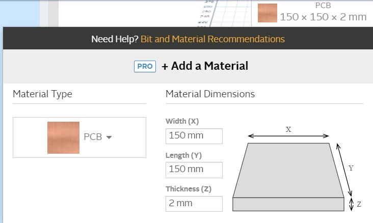
PCB coper sheet size and thickness.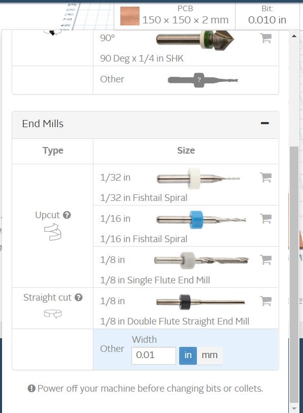
Milling bit.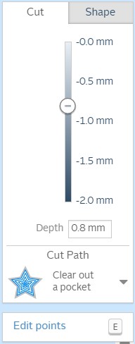
PCB milling depth.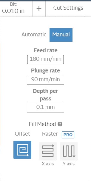
Setting for perfect milling by using Carvey machine.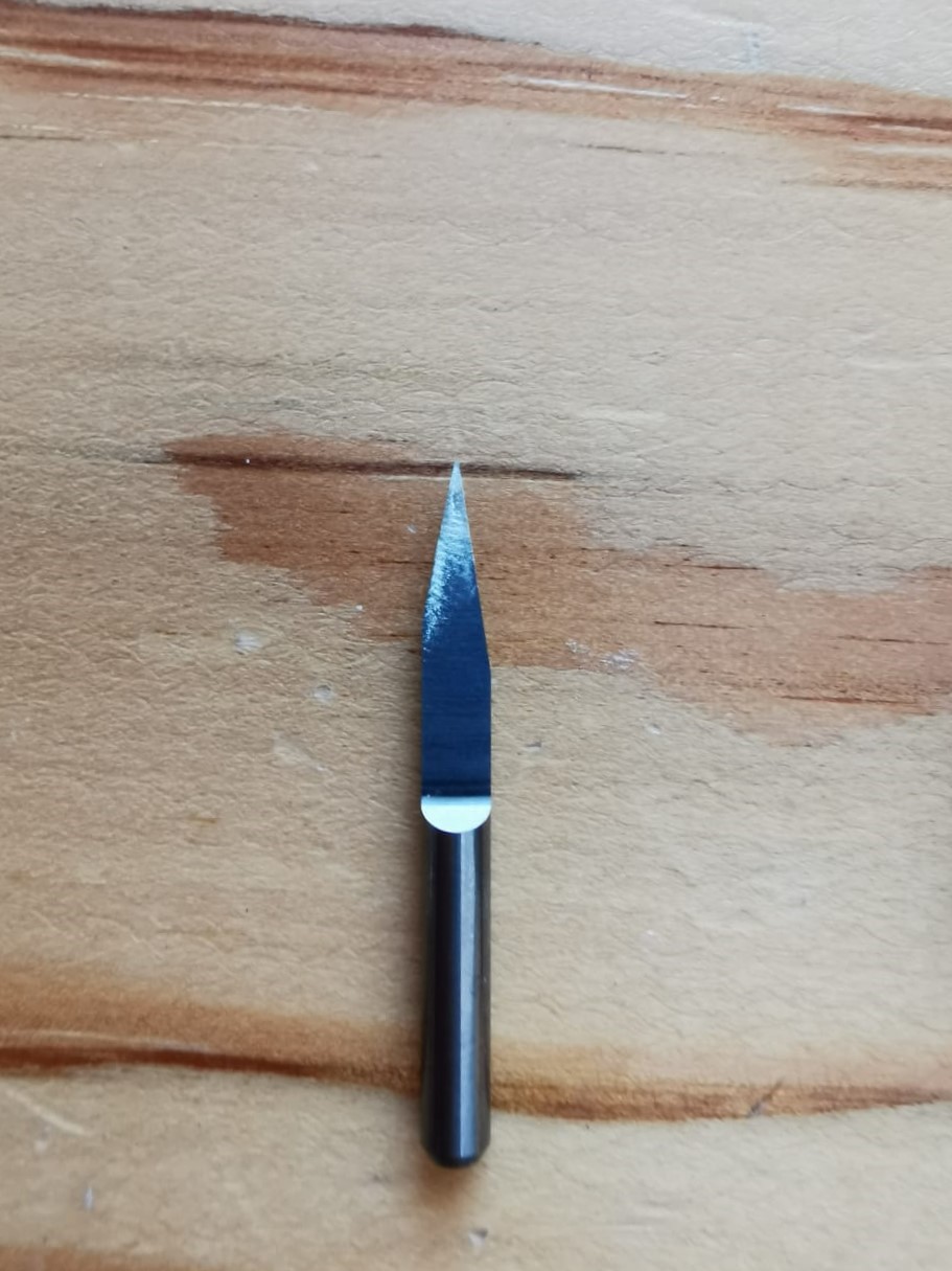
The milling bit. 1/64in
Outline Cutting - Bit : 1/32 in = 0.031 in
- Depth : 1.8 mm
- Depth per pass : 0.3 mm
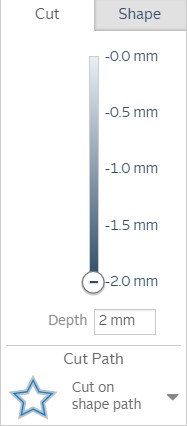
PCB cutting depth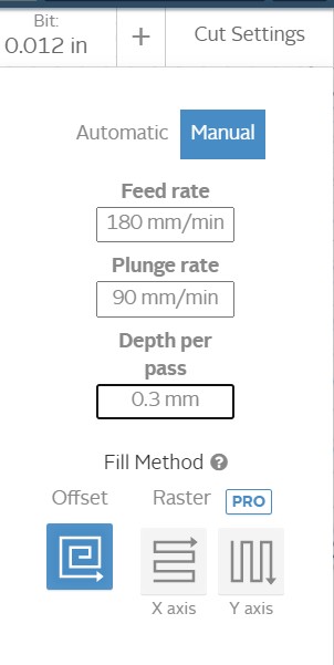
PCB cutting setting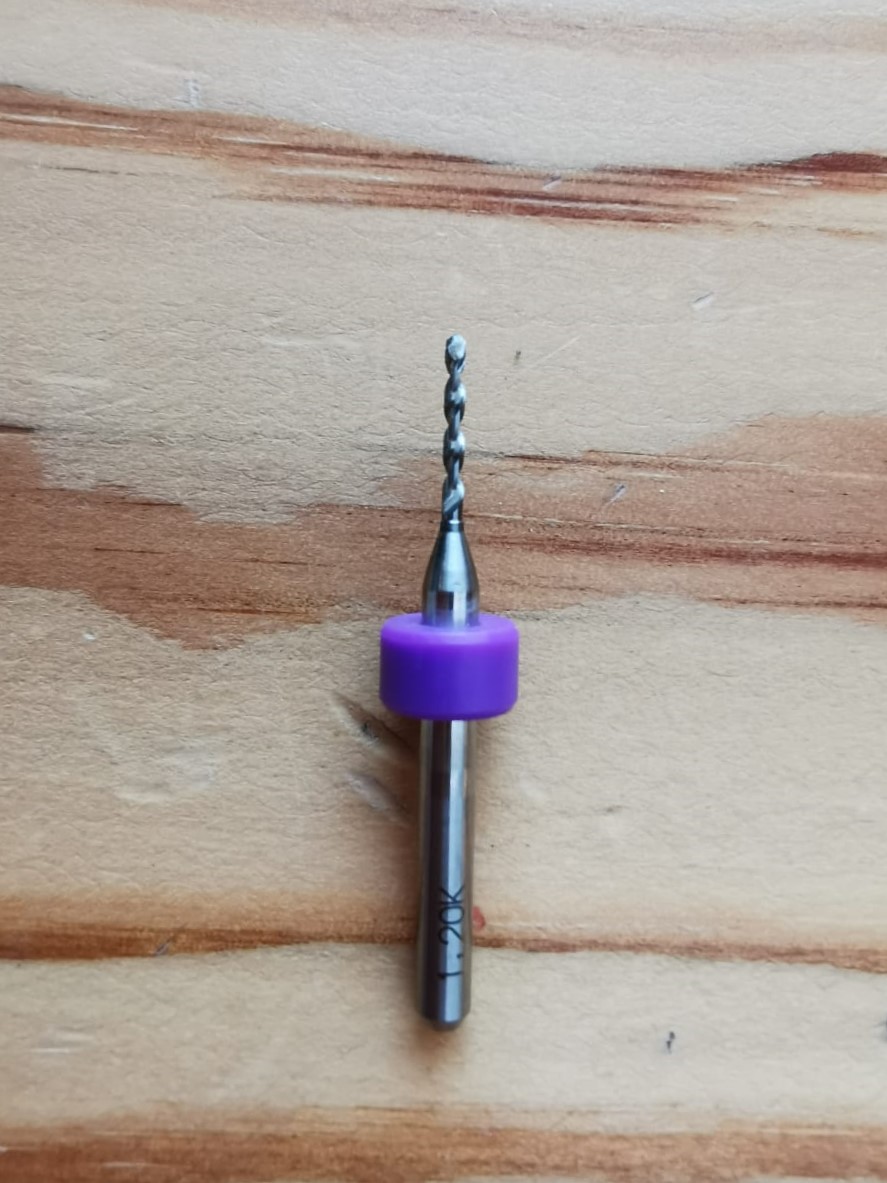
Cutting bit 1/32 in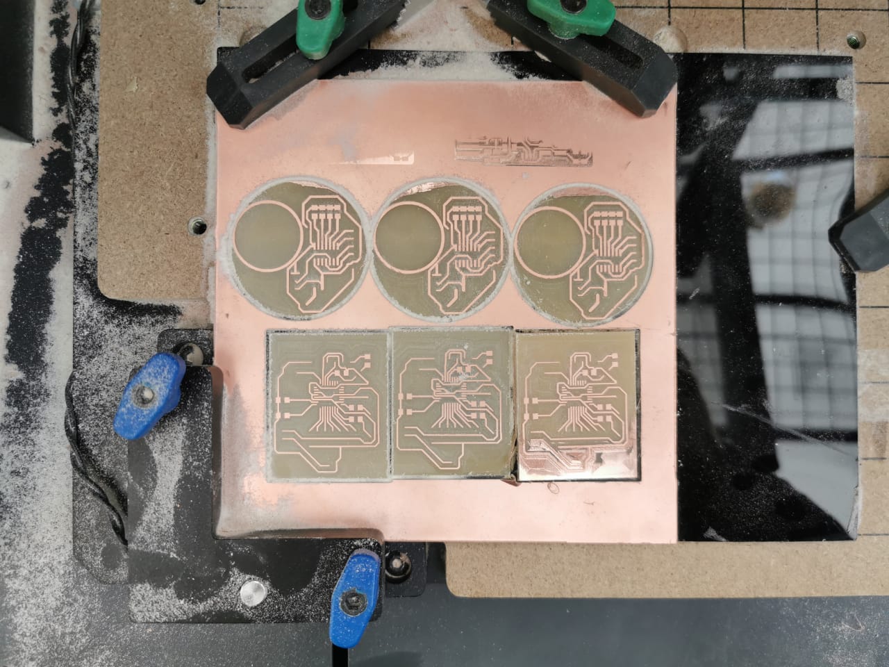
Final result
Soldering
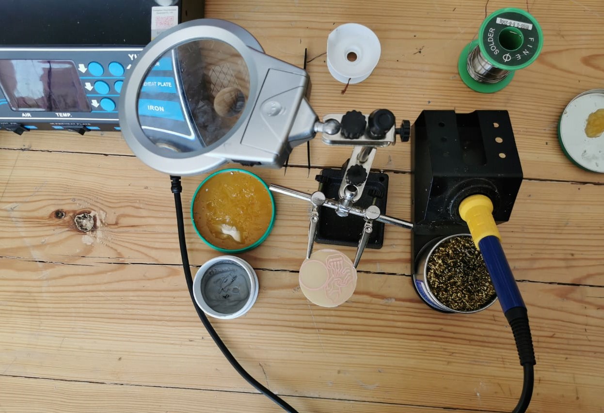
I used flux, soldering wire, and in some parts soldering tape. and for more control I used tweezers.
The Hydration bottel PCB Circuit
Always start with the microcontroller, I but some flux and a little bit of soldering wire in the tip of the soldering iron then I passed on the pins. I completed the soldering but I faced a problem with battery holder, it was bigger than I thought, so I used 3d printed holder I used before it works fine.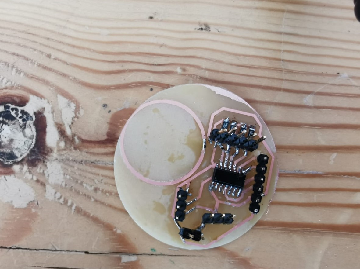
Almost done!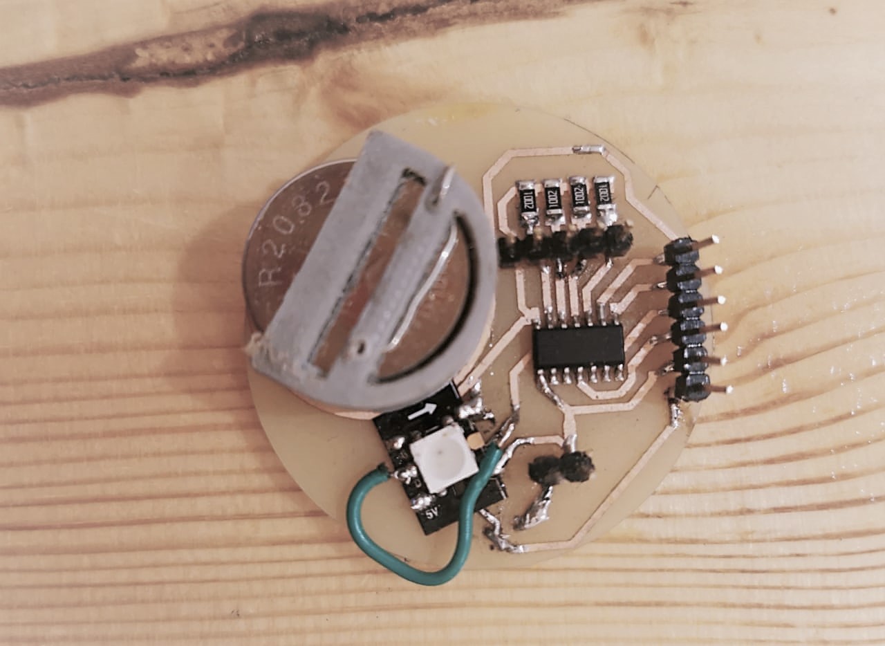
It's finlay ready.
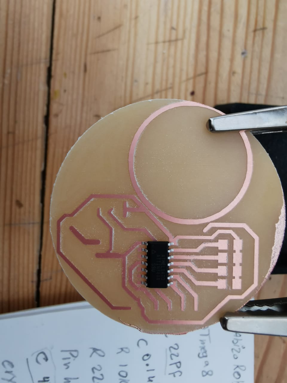
ABIZO Robot PCB Circuit
This PCB wasn't easy for the first time. I forget to disconnect overlap paths, so I used the heating gun to remove the microcontroller and do it again. I couldn't find lithium battery, so I decided to use a 5V adapter with 1-2A as output in this stage. This circuit took one whole week to completed to the end.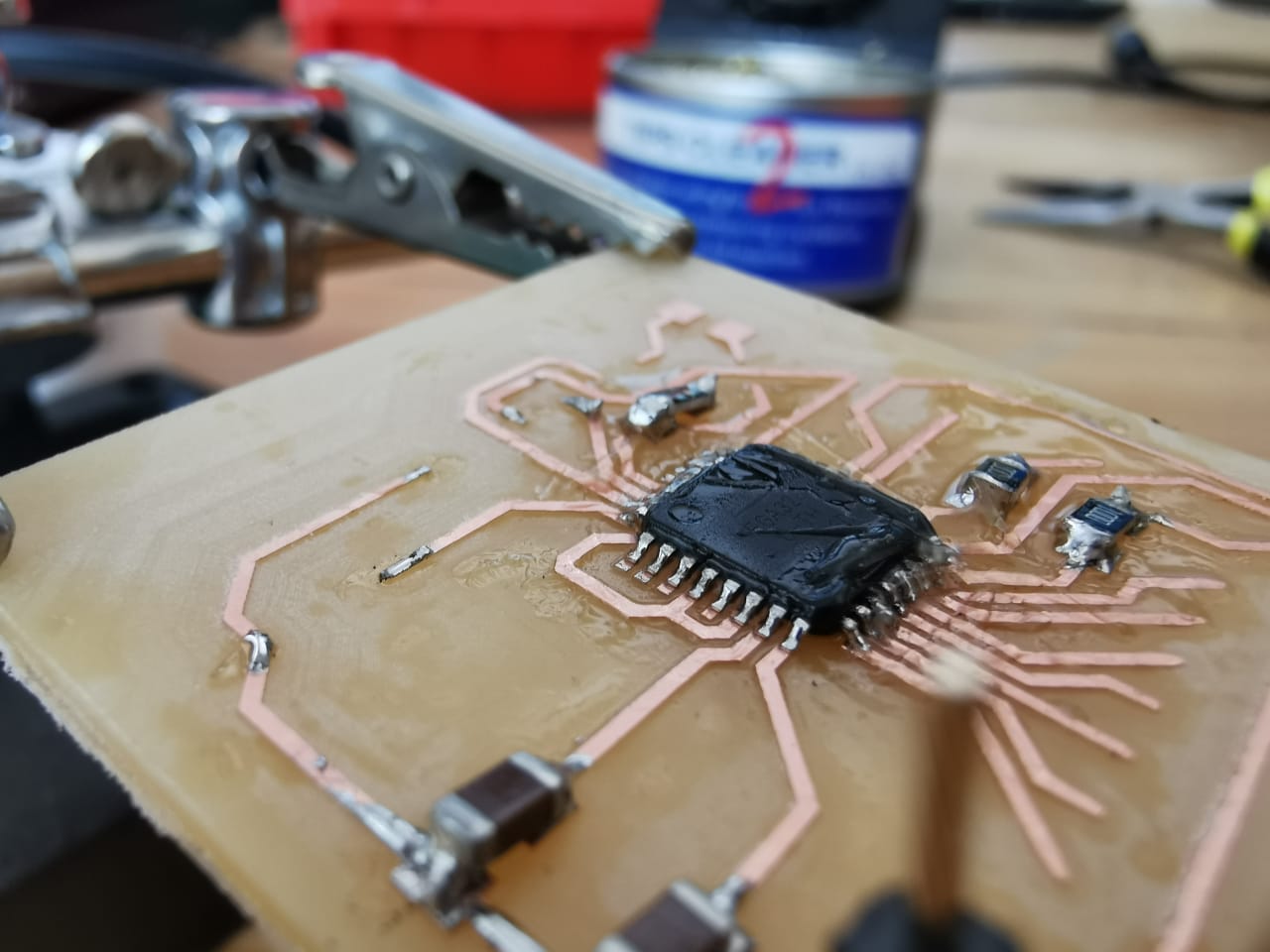
I started with the difficult part of the microcontroller.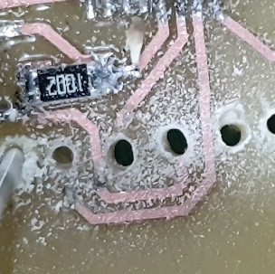
I ask for help to did the pins hloders holes, because when I tried to do it with the Carvey machine I breaked 3 bits.
Soldring the resisiters
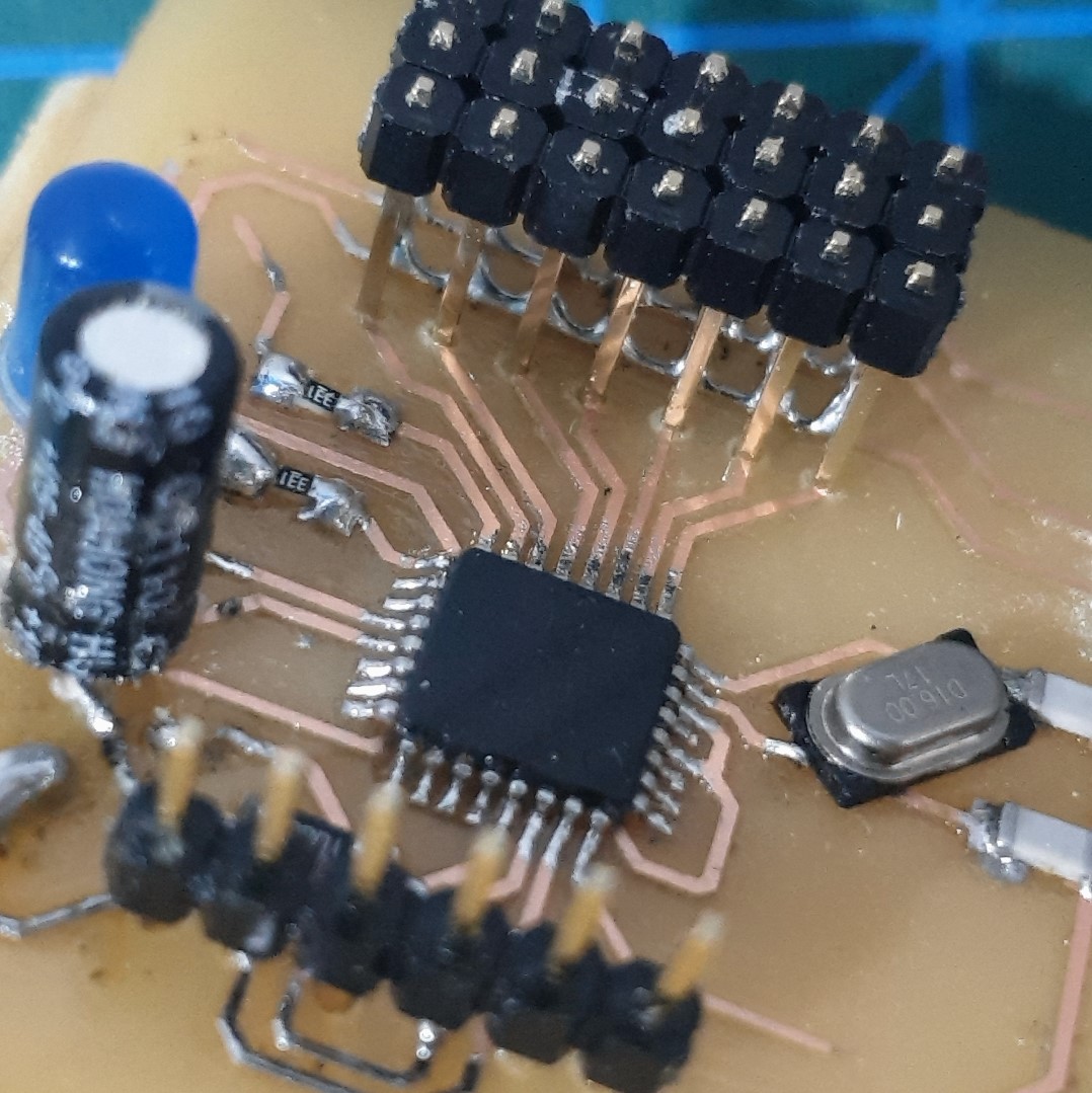
Assmbled most of the parts

Final result.
Programing
In this stage I will show the different codes I did to manage the electronics for this project, everything was coded by using Arduino IDE.
- The Hydration bottel PCB Circuit
Based on the Attiny 44 data sheet I/O pins.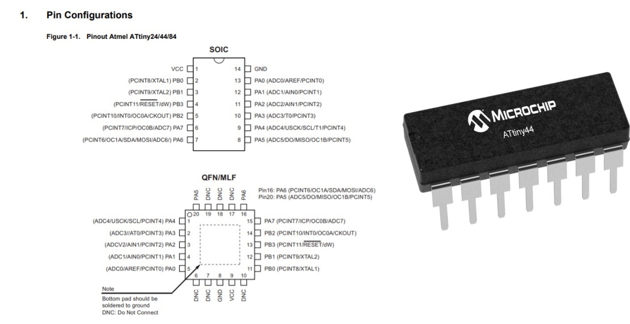
In this circiut I tryed before to program attiny digitaly by using Tinkercad on Embedded Programming week. and as a guied I followed the step on this link.
Code
In this code, I added Adafruit_NeoPixel.h library for controlling single-wire-based LED pixels. each water level has a different analog pin, each level has a different color. I was thinking of using jumper wires with different levels, or copper tape, but I took the advice to make a piece of PCB board with etching different levels, and it works.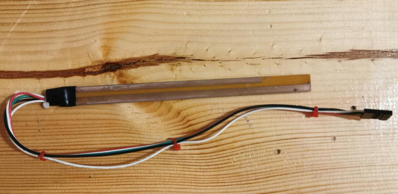
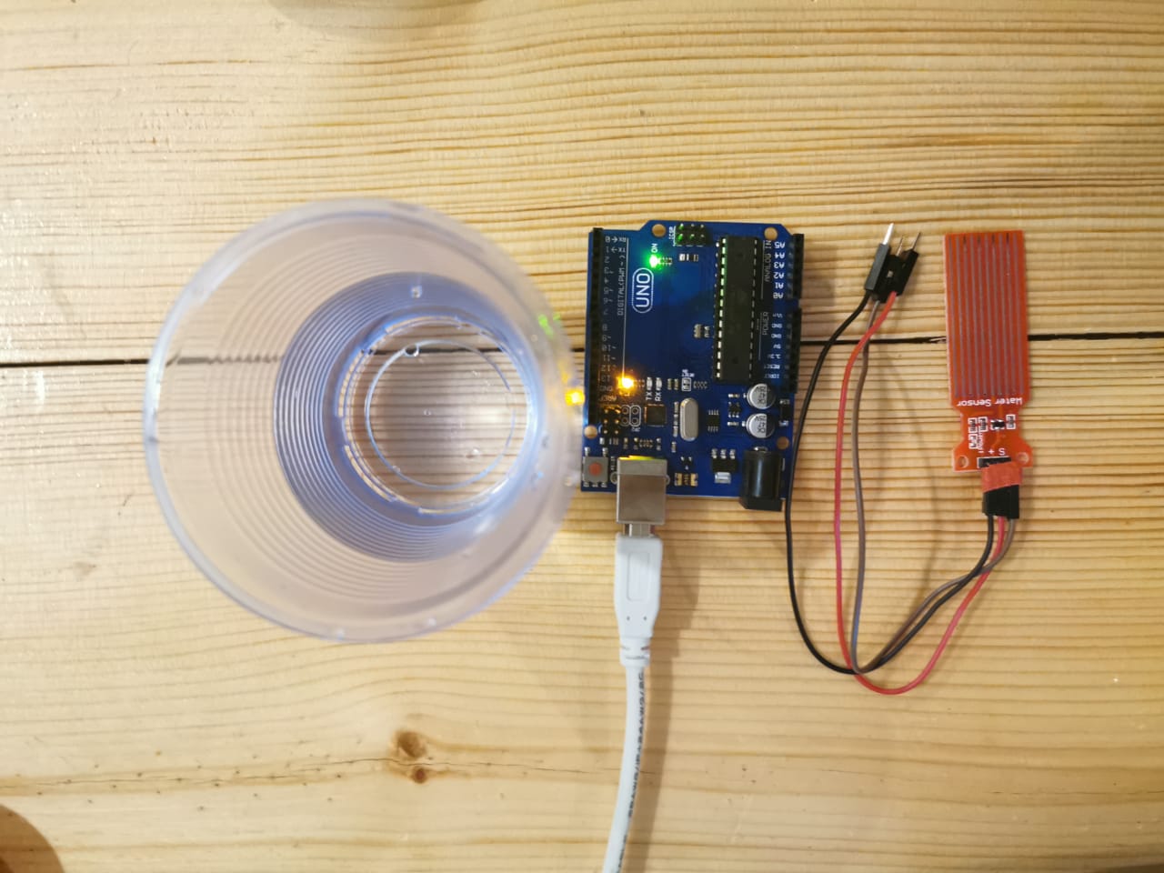
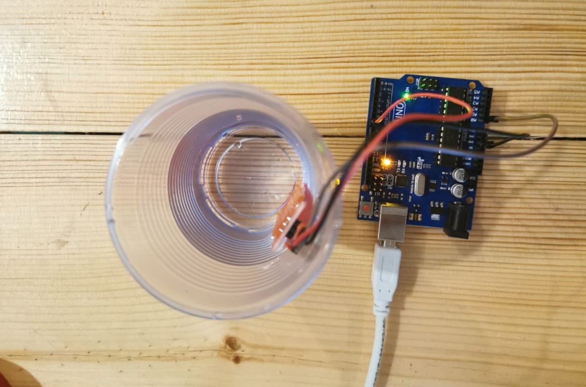
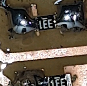
The sensor after atching and soldering the pcb boread.
Tesing the circuit.
- ABIZO Robot PCB Circuit
Based on the ATmega238p data sheet I/O pins.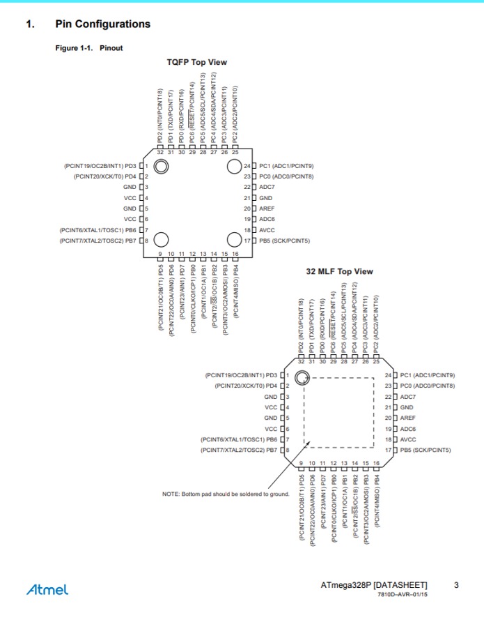
In this code, I used code written by Paul-Louis Ageneau for otto robot DIY teapot dancing robot, in this code I have added the ultrasonic sensor as input, and buzzer, 2 LED, 5x micro servos as output. When the sensor deducts the child, it will alarm by lighting up the led, moving the robot head, and buzzer. After the child sets for 45min -the average class time- it will do the special dance to ask him/her to move and do some exercises. I follow the steps in this useful link to load the code by using bootloader unlocker software tool.
Code Files: